Syllabus & Goals 3 min
Cambridge 10.1 · Standard logic gate symbols Paper 2 · Algorithms, Programming and Logic
By the end of this lesson you can:
- Explain what a logic gate, a logic circuit and a truth table are.
- Write every input combination for 2 or 3 inputs, in the correct counting order.
- Draw the symbols for NOT, AND and OR and complete their truth tables.
Textbook: Chapter 10, §10.1 and §10.2.1–10.2.3 (pp. 356–358)
Recap / Warm-Up 5 min
In Unit 8 you used AND, OR and NOT inside IF conditions. A condition is either TRUE or FALSE. Inside a computer, TRUE is stored as 1 and FALSE as 0. Logic gates are the hardware that does this reasoning.
Quick starter
A program runs IF Age >= 12 AND HasTicket = TRUE. Sam is 14 and has no ticket. Is the condition TRUE or FALSE?
Reveal the answer
FALSE. AND needs both parts to be TRUE. Sam's age part is TRUE but the ticket part is FALSE.
Key Concept 14 min
1 · Gates, circuits and truth tables
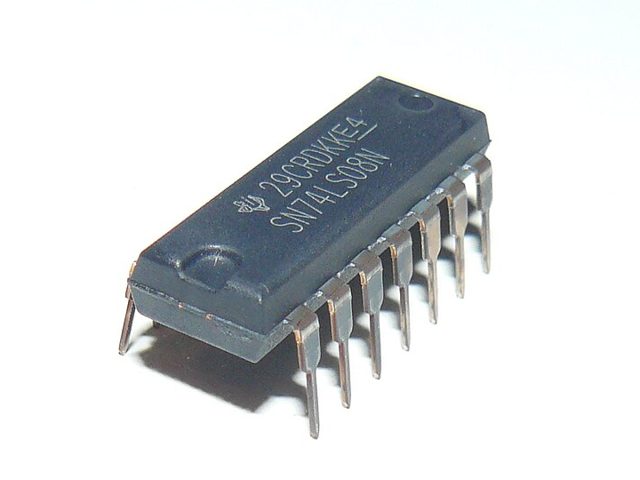
A logic gate is a tiny electronic circuit. It takes one or two binary inputs and gives one binary output. A 1 means on, high voltage or TRUE. A 0 means off, low voltage or FALSE.
Gates are joined together to make a logic circuit that does a job, such as switching on an alarm. Processors, memory and solid-state drives contain billions of gates.
2 · How many rows does a truth table need?
Each input can only be 0 or 1. So every extra input doubles the number of combinations. A table with n inputs has 2n rows.
| Inputs | Rows (2n) | Where you see it |
|---|---|---|
| 1 (NOT gate) | 2 | a single gate with one input |
| 2 | 4 | any single two-input gate |
| 3 | 8 | the largest circuits at IGCSE |
3 · The NOT, AND and OR gates
Cambridge uses these distinctive-shape symbols. Learn each shape, its rule and its truth table together.
NOT
The output is the opposite of the input. It is the only gate with one input.
| A | X |
|---|---|
| 0 | 1 |
| 1 | 0 |
X = NOT A
AND
The output is 1 only if both inputs are 1.
| A | B | X |
|---|---|---|
| 0 | 0 | 0 |
| 0 | 1 | 0 |
| 1 | 0 | 0 |
| 1 | 1 | 1 |
X = A AND B
OR
The output is 1 if either input is 1, or both are.
| A | B | X |
|---|---|---|
| 0 | 0 | 0 |
| 0 | 1 | 1 |
| 1 | 0 | 1 |
| 1 | 1 | 1 |
X = A OR B
Worked Example 12 min
(a) List every input combination for three inputs
- Count the inputs: A, B and C, so n = 3. The number of rows is 2n.
- Work out the rows: 23 = 2 × 2 × 2 = 8. Each input doubles the number of combinations.
- Fill column C (right-most) with 0 1 0 1 0 1 0 1. The last column changes every row, like the 1s column of a binary number.
- Fill column B with 0 0 1 1 0 0 1 1. It is the 2s column, so it changes every two rows.
- Fill column A with 0 0 0 0 1 1 1 1. It is the 4s column, so it changes every four rows.
- Check: each row is a different binary number from 000 (0) to 111 (7). No row repeats, so none is missing.
(b) Choose the gate for a scenario
- Decide what 1 means for each input: A = 1 means movement, B = 1 means the switch is pressed. Every input must have a clear meaning for 1 and 0.
- Go through each row. 0, 0: nothing happens, so X = 0. The light only reacts to one of the two events.
- 0, 1 and 1, 0: one event has happened, so X = 1. Either input is enough.
- 1, 1: both happened, so X = 1. "Or both" still switches the light on.
- The pattern 0, 1, 1, 1 is the OR gate: X = A OR B. Match the output column to a known gate.
| Inputs | Output | |
|---|---|---|
| A | B | X = A OR B |
| 0 | 0 | 0 |
| 0 | 1 | 1 |
| 1 | 0 | 1 |
| 1 | 1 | 1 |
Try It Yourself 12 min
Goal: Draw the symbol for an AND gate from memory. Label inputs A and B and output X. Then write its four-row truth table.
Goal: A logic circuit has four inputs, A, B, C and D. State how many rows its truth table has. Then write the first six rows in the correct order.
Goal: A lift door should close only when three conditions are all 1: the lift is empty of obstacles (A), the close button is pressed (B) and the lift is not overloaded (C). Each gate may have only two inputs. Sketch how two gates could produce X.
Hint
Join A and B with one gate first. Then feed its output and C into a second gate of the same type.
📝 Exam Practice 10 min
State the number of rows needed in a truth table for a logic circuit with three inputs.
Mark scheme
- 8 (23) (1).
A two-input gate gives the outputs 0, 0, 0, 1 for the inputs 00, 01, 10, 11. Identify the gate.
Mark scheme
- AND (1).
Draw the symbol for an OR gate with inputs A and B and output X, and complete its truth table.
Mark scheme
- Correct OR symbol: curved back, pointed front, two inputs, one output (1).
- Output column 0, 1, 1, 1 (1).
Describe the function of a NOT gate and of an AND gate.
Mark scheme
- NOT: has a single input (1)…
- …the output is the opposite / inverse of the input (1).
- AND: has two inputs (1)…
- …the output is 1 only when both inputs are 1, otherwise 0 (1).
Recap & Key Terms 3 min
Logic gates turn binary inputs into one binary output. A truth table lists all 2n input rows in counting order. NOT inverts, AND needs both inputs at 1, and OR needs at least one.
- Logic gate
- An electronic component that applies a logical operation to binary inputs to give one binary output.
- Logic circuit
- Logic gates joined together to carry out a particular task; its output is 0 or 1.
- Truth table
- A list of every possible combination of binary inputs and the output for each; n inputs give 2n rows.
- NOT gate
- One input; the output is the inverse of the input.
- AND gate
- The output is 1 only if both inputs are 1.
- OR gate
- The output is 1 if either input, or both inputs, are 1.
Homework 1 min
Task (≤ 15 min): A kettle heats (X = 1) when it contains water (A = 1) and the switch is on (B = 1). Name the gate, draw its symbol and complete a truth table. Then describe one other everyday device that behaves like an OR gate.
Model answer
- Gate: AND, because both conditions must be true.
- Truth table outputs for AB = 00, 01, 10, 11: 0, 0, 0, 1.
- OR example: a doorbell that rings from a front or a back button.