Challenge 1
Sketch your base robot from the side and from above. Mark where the drive wheels, the castor and the Colour Sensor go before you pick up a single brick.
Quick Learn — the model, the instructions, the program and the challenges. The theory is in Full Lesson.
EV3 Robotics›Level 4 · WRO Prep›Lesson 2
Level 4 · Lesson 2 · EV3-L04-0260 minutes · Block 1 of 6 · Mat: WRO 2021 — POWERBOTS, Energy at Home
Design a competition base robot for the 2021 mat — from a written brief, with no building instructions.
Every model in Levels 1 to 3 came with a manual. This one does not, and none of the next forty-six will. WRO hands a team a mat, a rulebook and a box of parts. What the robot looks like is the team’s problem, and it is the part judges care most about.
The brief. A two-motor driving base that fits inside the starting area, carries one downward-facing Colour Sensor, can follow a line, and has somewhere an attachment can bolt on without being rebuilt. It must survive being picked up by a ten-year-old.
A robot is designed for a mat, not in the abstract. Look at the 2021 mat in the picker below and pull out the constraints:
Those last two pull in opposite directions. That is normal. Write down which one you chose and why — the sentence is worth marks.
One rotation carries the robot one circumference. A 56 mm wheel travels about 176 mm per rotation; a 43 mm wheel about 135 mm.
This is the decision teams get wrong most often. The sensor must sit about 5–10 mm above the mat — too high and the reading washes out, too low and it scrapes.
Its distance in front of the drive axle is the real choice. A sensor far forward sees a line early and gives the robot time to react, but it also swings a long way sideways when the robot turns, which makes a line follower twitchy. Close in behaves the opposite way.
Traction comes from weight pressing the drive wheels down. Put the Brick — by far the heaviest part — over or just in front of the drive axle. A robot with the Brick hanging off the back spins its wheels when it starts and lurches when it stops.
Decide now where an attachment bolts on, even though you have not designed one yet. Two beams and two pins is enough. Teams that skip this rebuild the whole front of the robot in lesson 10.
A driving base has two Large Motors, one per wheel. You could drive them with two separate motor blocks — but they would never start at quite the same instant, and the robot would curve away. EV3 has a separate family of Movement blocks that treat the pair as a single driving base.
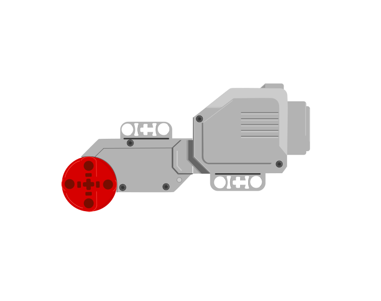 port Bport C
| Block | What it does |
|---|---|
set movement motors to [B v] and [C v] :: movement | Tells the Movement blocks which two ports are the driving wheels. Put it at the top of the program, before any movement. |
move [forward v] for (2) [rotations v] :: movement | Drives both wheels together, so the robot travels in a straight line. |
move for (1) [rotations v] at (75) (25) % speed :: movement | Drives the two wheels at different speeds, which makes the robot curve. |
set movement speed to (50) % :: movement | Sets how fast the driving base travels from now on. |
set movement motors to [B] and [C] is the block that decides which two motors every Movement block after it will drive. It does not look at the robot. It drives the two ports you name, whether or not there is a motor in them — so those two letters have to be the two sockets the cables are actually in.
This is the single commonest reason a driving base does nothing, and it is invisible in the program: every block is spelled correctly and the robot still will not go.
the same program on both robots
The yellow outline marks the two ports the block is driving. A robot only goes straight when both of them have a motor in them.
Both robots run the identical program. The left one has its motors in B and C, so both named ports have a motor and the robot drives straight. The right one is plugged into A and B: the block drives B, finds nothing in C, and never mentions the motor in A at all — so one wheel turns, one wheel sits there, and the robot swings round the dead one instead of driving.
If neither named port has a motor in it — cables in A and D, say, with the block still set to B and C — the robot does not move at all. The program runs happily to the end and the Brick reports nothing wrong, because as far as it is concerned it did exactly what it was told.
So before you look for a bug in the program, look at the cables: read the port letters off the Brick, then make the block say those two. B and C are only the usual choice, not a rule — if your build has the driving motors in A and D, set the block to A and D and everything works.
Everything a driving base can do comes from those two speed numbers. Try each button below and watch the trail the robot leaves.
The path is worked out from the two wheel speeds in the block, not drawn by hand — so changing the preset changes the numbers and the shape together.
Notice there is no steering block anywhere in that program, and no steering part anywhere on the robot. The turn is made entirely by driving the two wheels different amounts.
when program starts :: events hat
set movement motors to [B v] and [C v] :: movement
move [forward v] for (2) [rotations v] :: movement
move for (1) [rotations v] at (50) (-50) % speed :: movement
“Move forward 2 rotations” says nothing about the floor — it says how many times the wheels go round. How far the robot actually travels depends on how big the wheels are, and once round a standard EV3 driving wheel is about 17.5 cm.
Before doing any sums, get a feel for it. Drag the robot along and watch both scales at once — rotations on top, centimetres underneath, the same line. Land on the half marks: there is a number between 1 and 2, and it is 1.5.
Drag the robot, or use the arrow keys — it moves in half rotations. Rotations above the line, centimetres below.
1.5 — a half rotation past 1. Half a turn of the wheels is 8.75 cm, so halves matter.
35 ÷ 17.5 = 2. That is a number you can type straight into the block.
set movement motors to [B v] and [C v] :: movement
set movement speed to (30) % :: movement
move [forward v] for (2) [rotations v] :: movement
Steering at right 100 or left 100 drives the two wheels in opposite directions, so the base stops travelling and pivots where it stands. The angle it sweeps is a simple doubling of the rotations:
Half a rotation is the one worth remembering: a square corner, 90°.
| Rotations | The robot turns |
|---|---|
| 0.25 | 45° — half a corner |
| 0.5 | 90° — a square corner |
| 1 | 180° — turn round and face back |
| 2 | 360° — all the way round |
The one to memorise is 0.5 rotations = 90°. Everything else follows from doubling or halving it.
set movement speed to (20) % :: movement
move [right: 100] for (0.5) [rotations v] :: movement
Turn slowly. The wheels on a driving base are big and the robot carries a lot of weight, so at full speed it keeps going after the motors stop and lands past the angle you asked for. Somewhere between 15% and 30% speed is where turns become repeatable. A turn that overshoots is almost always a turn taken too fast, not a wrong number.
These figures belong to your robot. The distance depends on the wheels and the angle depends on how far apart they are, so a wider base needs a different number for 90°. Test it, measure what actually happened, and adjust — the same discipline as the Gyro Sensor tolerance.
Every wheeled vehicle steers this way — a tank, a digger, an office chair with two driven castors. Cars use a steering rack instead, but a robot that turns by driving its wheels at different speeds needs no steering mechanism at all.
The Colour Sensor looks down at a surface and can answer three quite different questions: what colour is this?, how bright is this? and how light is the room? Choosing the wrong one is the usual reason a line-following robot refuses to work.
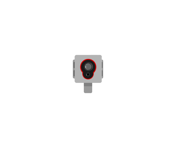 front
front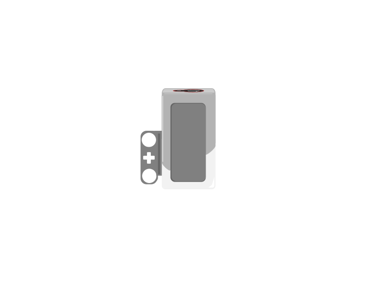 side
side| Block | What it does |
|---|---|
([3 v] color :: sensors) | Reports which colour it sees, from a short list — red, blue, green, black, white and a few more. |
([3 v] reflected light intensity :: sensors) | Reports how bright the surface is, as a number from 0 (black) to 100 (white). |
<[3 v] is color [red v]? :: sensors> | Reports true or false for one particular colour. |
([3 v] ambient light intensity :: sensors) | Reports how much light is falling on the sensor, 0 to 100, with its own lamp switched off. |
The sensor does not describe a colour — it picks one from a list of eight, and that list is the whole of what it can ever say:
| Reports | Means |
|---|---|
| 0 | no colour — too far away, or too dark to call |
| 1 · 2 · 3 | black, blue, green |
| 4 · 5 · 6 | yellow, red, white |
| 7 | brown |
Anything you put under it is forced into one of those eight. There is no orange and no purple: an orange brick comes back as red or as yellow, and often as red one moment and yellow the next as the robot creeps along. Light blue and grey are the other classic pair to avoid — grey is neither black nor white, so it flips between them.
This is why colour mode is a good fit for a task you control and a bad fit for one you do not. Sorting the LEGO bricks that come in the set works, because they are made in exactly these colours. Reading a printed sheet, a coloured tile from another set, or anything pastel is asking the sensor to answer a question it does not have a word for.
Two practical points follow from how it decides. It shines its own lamp and looks at how much red, green and blue comes back, so it must be close — about half a centimetre, and no more than a centimetre. Lift it and the answer decays to 0. And because it takes those three readings before it can answer, colour mode is the slowest thing this sensor does; a robot driving quickly can pass right over a small patch without ever reporting it.
When a colour must be recognised reliably, test it. Drive the robot slowly over the real surface with color shown on the screen and watch what it actually says — including what it says at the edges between two colours, which is where the wrong answers live.
Both questions are asked of the same surface at the same moment. Watch the two answers travel across a strip of colours and then over the edge of a black line.
Watch the two read-outs over the last third of the strip. One of them changes once. The other changes the whole way across.
Over the patches, both read-outs are useful. Over the edge of the line they part company: the colour name has only two answers to give and jumps between them, while the number slides smoothly from 88 down to 8. Every value in that slide tells you how far onto the line the sensor is — which is information the name simply does not carry.
A line follower built on colour names only knows “black” or “not black”, so it can only lurch. Built on reflected light it can tell how far onto the line it has drifted, which is what makes smooth following possible.
The first two modes both switch the sensor’s own lamp on and measure what bounces back off the surface. Ambient light intensity does the opposite: the lamp goes off, and the sensor simply reports how much light is arriving from wherever — 0 in the dark, up to 100 in bright light.
| Mode | Own lamp | Measures | Points |
|---|---|---|---|
| colour | on | which of eight colours the surface is | at the surface, very close |
| reflected light | on | how much of its own light comes back | at the surface, very close |
| ambient light | off | how bright the surroundings are | wherever you want to measure |
That makes it the only one of the three that is not really about the floor. A number between 0 and 100 means very little on its own, so watch the same sensor sit through five different rooms — nothing underneath it changes at any point.
the sensor’s own lamp is off — it is measuring the room
Nothing under the sensor changed at any point in this run. Ambient light is the one mode that is not asking about the surface at all.
Those are the shape of the scale rather than exact figures, but the shape is the useful part: a lit room is nowhere near 100, and the top of the range is reserved for a light pointed straight at the sensor. Cover it with your hand and the number drops to near zero — which is the easiest way to check the sensor is doing what you think.
Point it at the ceiling and it tells you whether the room lights are on; point it forwards and a torch will spike the reading, which is a way of signalling to a robot without touching it.
Do not reach for it as a substitute for reflected light. Room light falling on a black line and on white paper is almost the same, so ambient mode can barely tell them apart — the reason reflected light works is precisely that the sensor brings its own light and measures how much of it survives.
It is also the mode most at the mercy of the room. A reading taken by a window in the morning will not match the same spot in the afternoon, so anything built on ambient light needs measuring on the day, in the place, with the lights as they will be.
Even the two lamp-on modes are affected by room lighting — a reading taken by a sunny window differs from one taken in a corner. The sensor must also sit close to the surface and at a constant height, because lifting it changes the reading even though the surface has not changed.
There are two ways to tell an EV3 motor how much to move: give it a length of time, or give it an amount of turn. Only the second one is repeatable, and that difference decides whether a machine works reliably or only sometimes.
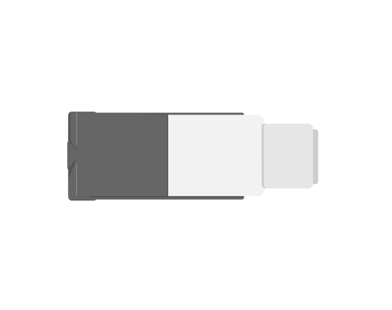
| Block | What it does |
|---|---|
[A v] run [clockwise v] for (1) [rotations v] :: motors | One full turn of the motor shaft, then stop. The program waits for it. |
[A v] run [clockwise v] for (180) [degrees v] :: motors | Half a turn. 360 degrees is one rotation. |
The counters below tick up in step with the shaft, so you can watch a rotation being counted rather than take it on trust.
the same movement, written in degrees
The two motor read-outs are the same measurement — 1 rotation is 360°. Use whichever makes the number easier to read.
Notice that the two motor counters finish together: 2.00 rotations and 720° are the same instant, because they are the same measurement in different units. So pick whichever makes the number easier to read. A winch that needs eight full turns is clearest in rotations. A gate that lifts a quarter turn is clearest in degrees — 90 rather than 0.25.
The third counter is the one that catches people out. The block counts turns of the motor, not of the thing it drives — and the gear in the demo is three times the size, so two motor rotations move it only 0.67 of a turn. Ask for two rotations and the mechanism does not move two rotations’ worth unless the gearing is one to one.
That is why a number that works on one build has to be retuned when the gearing changes — the program is right, the mechanism is different.
A printer feeds paper an exact distance; a lift stops level with the floor; a robot arm returns to the same place a thousand times. None of that is possible by timing a motor — they all count turns.
Two drawings, on paper, before any brick is picked up: a side view and a view from above.
| Port | What is plugged in | Why that port |
|---|---|---|
| B | Left drive motor (Large) | B and C are the course’s drive pair, in every level |
| C | Right drive motor (Large) | Paired with B so movement blocks work unchanged |
| A | Attachment motor (Medium) — reserved | Left free today; lesson 10 fills it |
| 3 | Colour Sensor, facing down | Port 3 is the colour port throughout the course |
| 2 | Gyro Sensor — reserved for Block 3 | Leave the port and the space; Block 3 needs it |
Reserve the Gyro space now. Block 3 bolts a Gyro Sensor flat to the chassis. A team that fills every stud today will be dismantling its robot in lesson 19.
You are not programming yet, but the design has to make this program possible. Read it and check your sketch can run it.
when program starts :: events hat
set movement motors to [B v] and [C v] :: movement
move [forward v] for (2) [rotations v] at (40) % speed :: movement
stop moving :: movement
Three questions to ask of the drawing:
Trade sketches with another team. Each team makes exactly one written criticism of the other’s design, in this form:
“Your Colour Sensor is 30 mm in front of the axle. On the tight approach to B that will swing wide. Try 15 mm.”
Naming the part, the consequence and a suggested change is what makes it a design review rather than an opinion. Then decide whether to take the advice, and write down your decision either way.
Cut a rectangle of paper the size of your top view. Put it on the mat and slide it round the route you planned in lesson 1.
A rectangle of paper costs nothing and finds the size problem that would otherwise cost you lesson 3.
Entry 2 is the design record. It must contain:
If your journal shows one design that was right first time, a judge cannot tell whether you engineered it or copied it. Showing the wheel size you did not pick, and why, is evidence that a decision happened. Keep your rejected sketches — do not tidy them away.
This model drives, so its challenges are run on a mat. Mats differ between branches — check you are looking at the one in your room.
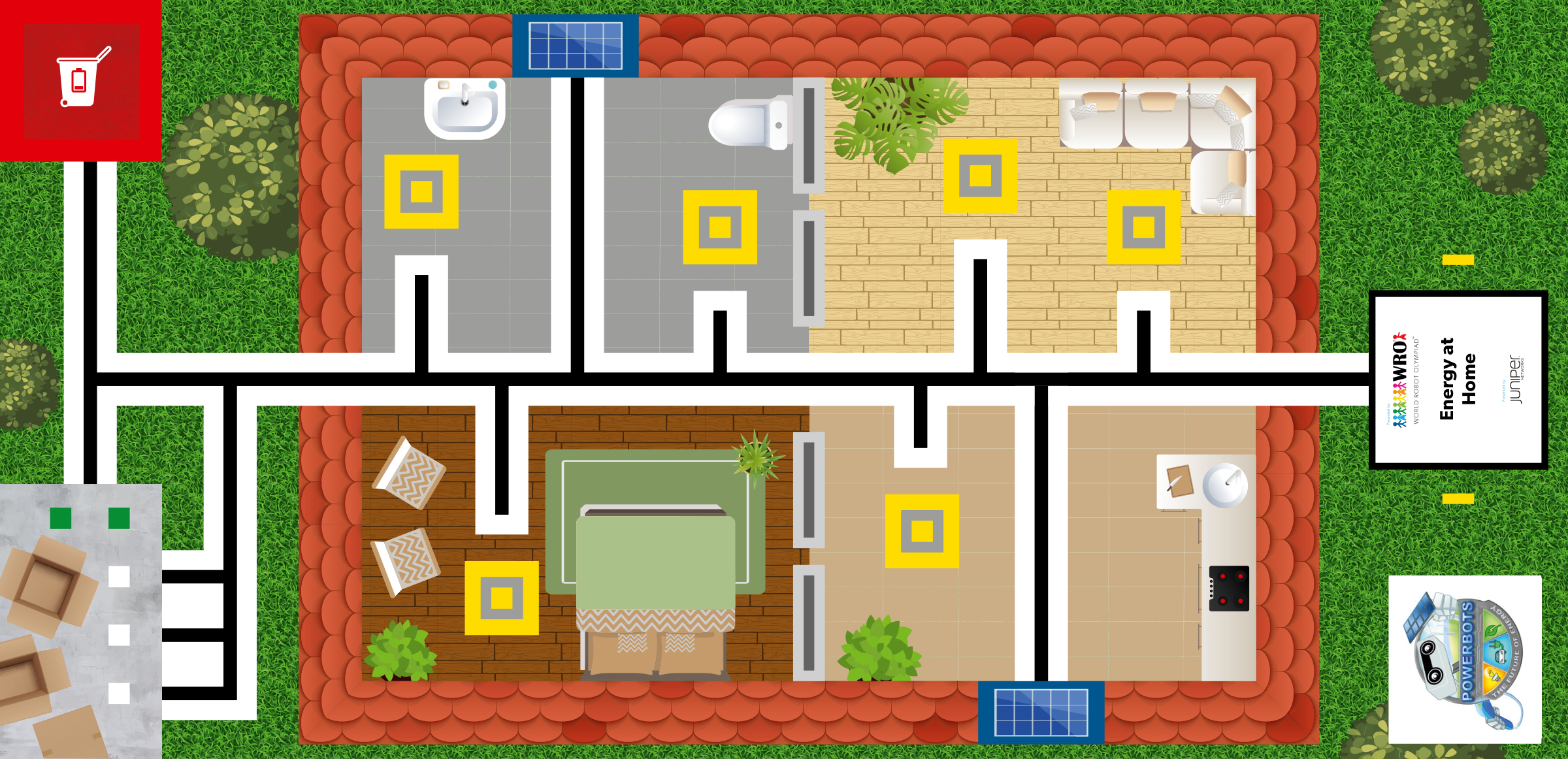
WRO 2021 RoboMission Elementary — POWERBOTS — Energy at Home · official WRO game mat, 2362 × 1143 mm
The challenges name these places rather than distances, so the same challenge works on any mat:
Work through them in order — each is harder than the last. The extra challenge comes after all three, and it is meant to make you plan before you build.
Sketch your base robot from the side and from above. Mark where the drive wheels, the castor and the Colour Sensor go before you pick up a single brick.
Justify the wheel size you chose in one sentence: a big wheel travels further per rotation, a small wheel turns more accurately.
Move the Colour Sensor 1 cm further forward on your sketch and say what that changes about how early the robot sees a line.
Produce a build brief another team could follow: a labelled sketch, the port table, the wheel diameter in millimetres, and the reason for each choice. It must fit on one side of paper.