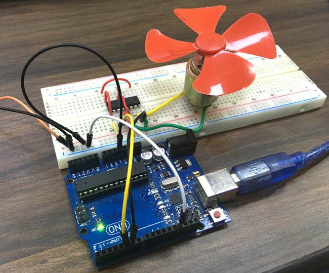
An Arduino pin can supply about 20 milliamps. A TT motor — the yellow gearbox on every classroom robot — draws about 150 mA running free and up to 1.5 A the instant you hold its wheel. Wire one to a pin and you do not get a slow motor. You get a dead pin, and usually a dead board.
So the motor never touches the Arduino. A motor driver sits between them and does the one job the Arduino cannot: hold a big current on and off. The Arduino sends signals; a battery pack supplies the muscle. Two separate worlds, joined at exactly one point — a shared ground.
Why it is called an H-bridge. Inside are four switches around the motor, arranged like the letter H with the motor as the crossbar. Close the top-left and bottom-right pair and current crosses the motor one way. Close the other pair and it crosses the other way. Same motor, same battery, opposite direction — and that is the thing a single transistor cannot do.
Two wires per motor, and they do both jobs at once. This is the part that surprises people who have met older drivers. The Maker Drive has no enable pin and no speed pin. Each motor gets two inputs — M1A and M1B — and both accept PWM:
Whichever input you drive decides the direction.
How hard you drive it decides the speed.
analogWrite(M1A, 200) with M1B at LOW means forwards, fairly fast. Swap which pin gets the number and the motor runs backwards. One idea, two pins, no third wire.
The board has two channels — M1A/M1B for motor 1 and M2A/M2B for motor 2 — because two motors is what a robot with two wheels needs. This lesson uses channel 1; the extra challenge finally uses both.
Fullscreen it while you build — you can pause and scrub with the player's own controls.
What you will be able to do
By the end of this lesson you can:
Say why a motor cannot be wired to an Arduino pin, in milliamps.
Name every pin and terminal on the driver: VB+, VB-, the motor outputs, and the M1A, M1B, 5VO, GND, M2A, M2B header.
Wire a battery, a motor and an Arduino to the driver with a common ground.
Choose the direction by picking which of the two inputs you drive.
Set the speed with analogWrite() on that same input, and explain why small numbers do nothing.
Read the truth table and say what LOW/LOW and HIGH/HIGH each do.
Say why both inputs of a channel must be on PWM-capable pins.
What you need
Part
Type
Qty
Arduino UNO R3
Microcontroller
1
USB A to B cable
Cable
1
Maker Drive H-bridge motor driver
Motor driver
1
TT gear motor with wheel, 3-6 V
Motor
2
AA battery holder, 4 cell
Battery
1
Jumper wires, male to male
Wiring
8
Jumper wires, male to female
Wiring
4
Solderless breadboard, 830 point
Prototyping
1
Push button, tactile
Input
2
Wiring Diagram
Unplug the USB cable and take the battery out before you build. Unlike every lesson before this one, there is a supply on the bench that can melt a wire.
You will need a small screwdriver: the motor and battery go into screw terminals, not breadboard holes.
The driver is a Cytron Maker Drive. Any H-bridge board whose four inputs all accept PWM will do — the sketches below work unchanged.
Basic
The truth table
Everything the driver does comes out of this. Input A is M1A and Input B is M1B:
Input A
Input B
The motor
LOW
LOW
brakes — both sides shorted, it stops dead
HIGH
LOW
turns one way
LOW
HIGH
turns the other way
HIGH
HIGH
coasts — outputs let go, it slows down on its own
Read the middle two rows again. There is no separate direction pin and no separate speed pin: the input you drive is the direction, and how hard you drive it is the speed.
Nobody can tell you which way "one way" is. It depends on which motor lead went into which screw. Try it, and if forwards is backwards, swap the two motor leads at the terminal — that is the fix, not a change to your sketch.
Speed is the same two pins
analogWrite(M1A, 200) with M1B at 0 means forwards, fairly fast. The numbers are not a percentage of speed:
analogWrite(M1A, …)
What actually happens
0
stopped
60
usually nothing — it hums and sits still
100
starts to crawl
150
a comfortable working speed
255
full speed
The dead patch at the bottom is real and it is not a fault. A motor has to overcome the friction of its own gearbox before it turns at all, so the first third of the range is spent getting nowhere. You will measure yours in Challenge 1.
So what is analogWrite() actually doing?
Here is the thing the name gets wrong. analogWrite() sounds like it sets a voltage — 128 ought to mean two and a half volts. It does not, and it cannot. A digital pin has exactly two settings: 0 V and 5 V. There is no dimmer inside it.
Challenges
Challenge 1
Find the floor.
Keep the motor turning one way — M1B stays at 0 throughout — and stop changing direction. All this sketch does is set a speed.
Start at analogWrite(M1A, 0) and go up ten at a time, waiting a second at each step, until you reach 255. Then start again from 0.
Watch the wheel and write down two numbers:
The value where the motor first moves at all.
The value where it moves smoothly rather than jerking.
Then lean a finger gently on the wheel and run it again. Both numbers go up.
Think about it: if 0 to 70 does nothing, your throttle really only has about 185 useful steps, not 255. Remember that in Challenge 2.
Topics you need for this one:
→ The for Loop — counting 0, 10, 20 … 255 without writing twenty-six lines.
Log in to ask for the answer.
Challenge 2
Two buttons, faster and slower.
Add button A on pin 2 and button B on pin 3, both INPUT_PULLUP, on the breadboard. Direction stays fixed, so M1B stays at 0.
Button A speeds the motor up.
Button B slows it down.
Keep the speed in a variable and change it by 25 on each press. Then send it to the motor with analogWrite(M1A, speed).
Stop it running off either end: never above 255, never below 0. Press A twenty times and the motor must not start behaving strangely.
You already know how to make one press count as one press — it is the while loop from ARD-PR-02, and you will need it on both buttons.
Then make it feel better. Start the speed at the floor you measured in Challenge 1 rather than at 0, so the very first press already turns the wheel instead of doing nothing three times.
Topics you need for this one:
→ Compound Operators — and .
→ — stopping at each end of the range.
→ — one press, one step.
Extra challenge
Drive a square, on demand.
Time to use the second half of the board. Wire the second motor to the MOTOR 2 terminal; its inputs are already on D5 and D6 from the wiring diagram.
Sit both motors on a chassis, or just tape them to a box so you can see the wheels.
Press button A and the machine drives a square: forwards for two seconds, turn ninety degrees, four times, then stop and wait for the next press. Nothing moves until you ask it to.
A two-wheeled machine turns by driving its wheels differently — one forwards and one backwards spins it on the spot; one stopped and one going swings it round in an arc. Try both and pick.
Ninety degrees will be a number of milliseconds you find by guessing, testing and adjusting. It will not be exact, and it will change when the battery drops or you move onto carpet.
Write the moves as functions — forward(), turnRight(), halt() — before the sketch turns into a wall of analogWrite(). Four sides means the same two moves four times, so a for loop should run them.
Think about it: your square does not close, and every lap it gets worse. Nothing is broken. The wheels are being told how long to turn, never asked how far they went, so every small error is kept for ever. Look at what a rotary encoder does in ARD-PR-21 and you will see what is missing.
Five wires and only five. Four carry PWM to the driver's inputs; the fifth is the common ground, without which none of the other four mean anything. The battery and the motor never reach the breadboard — they go into the screw terminals along the top of the driver, drawn here as the pigtails leaving it. 5VO is left unconnected: the Arduino already has power from USB.
The driver, and what is on it
Part of the board
What it is
Power input terminal
VB+ and VB-. Battery + to VB+, battery − to VB-
Motor output terminals
one 2-way terminal per motor. Either way round — swapping them reverses the motor
Input header
M1A, M1B, 5VO, GND, M2A, M2B
Test buttons
four of them, two per motor. Press one and the motor runs at full speed with no sketch at all
Status LEDs
four, two per motor. They light when that input is driven
Power LED
on when the battery is connected
The test buttons are the best feature on the board for a beginner. Press one before you write a line of code: if the motor turns, your battery, wiring and motor are all good, and anything that goes wrong afterwards is in the sketch.
Connections
From
To
Note
Battery +
driver VB+
6 V from four AA cells
Battery −
driver VB-
screw terminal
Motor lead 1
motor 1 terminal, first screw
either way round
Motor lead 2
motor 1 terminal, second screw
—
Arduino GND
driver GND
the common ground — see below
Arduino D9
driver M1A
direction and speed, one way
Arduino D10
driver M1B
direction and speed, the other way
Arduino D5
driver M2A
second motor, extra challenge only
Arduino D6
driver M2B
second motor, extra challenge only
All four signal pins must be PWM pins. On an UNO those are the ones marked ~: 3, 5, 6, 9, 10 and 11. Both inputs of a channel carry the speed, so putting one of a pair on a plain pin gives you a motor that runs full speed one way and only full speed the other.
There is no 5 V wire, and that is not an oversight. The driver has no 5 V input. It takes all its power from the battery at VB+ / VB-, and that one supply runs both the H-bridge and the board's own logic. Its inputs are happy with anything from 1.7 V to 6 V as a HIGH, so it never needs to be told what voltage your controller runs at.
5VO points the other way: it is 5 V coming out of the driver, up to 200 mA, so a finished robot can run its Arduino off the motor battery and carry one power source instead of two. Leave it unconnected here — USB is already powering the Uno, and two supplies pushing on one 5 V rail is how boards die.
The ground wire is a different matter and you still need it. HIGH is only meaningful as a voltage measured against something, and without a shared zero the two boards have no agreed something. That is why this diagram has five wires and not four.
Which battery
The motor is rated 3 to 6 V. The driver accepts 2.5 to 9.5 V.
Four AA cells (6 V) is the right pack for this lesson. Both parts are happy and full speed is genuinely full speed.
Two 18650 cells (7.4 V) works and the driver is fine with it, but it is above the motor's rating. Keep analogWrite() at 200 or less and you are back inside 6 V on average.
Check before power.
Arduino GND to driver GND. Miss this and there is no shared zero for the signals to be measured against. The motor twitches, runs at random, or does nothing — and every wire looks right. It is the commonest fault on this bench by a distance.
Nothing from the motor or the battery touches the Arduino. If a motor lead or a battery wire is in the Uno, stop and rebuild.
Screws tight, no loose strands. One stray whisker across a motor terminal shorts the channel.
Battery polarity into VB+ and VB-. This board has reverse-polarity protection and will survive the mistake, which is exactly why you should still get it right — the protection is there for the day you are tired, not as a way of working.
Motor free to spin. Wheel over the edge of the desk, or the motor drives itself off the bench.
Plug the USB in first, then the battery. On the way down, battery out first.
What it changes is how much of the time the pin is at 5 V. It switches the pin on and off, over and over, far too fast to see, and the number chooses how much of each cycle is spent on:
The solid line is what the pin is really doing — 0 V or 5 V, never anything between. The dashed line is the average, and the average is what the motor feels. This is called PWM, pulse width modulation: the width of each pulse is what changes.
Follow one row across. The pin snaps to 5 V, sits there, snaps back to 0 V, sits there, and repeats. It never once stops at 2.5 V. Now look down the rows: as the number rises the on part gets wider, and the dashed average line climbs with it.
Why the motor does not judder. It is being switched on and off about 490 times a second on pins 9 and 10 — and about twice that on pins 5 and 6, because the UNO's timers differ and no motor can tell. Either way, a motor with a gearbox and a wheel on it is far too heavy to start and stop that quickly. It has barely begun to slow down before the next pulse arrives, so it settles at a speed that matches the average — as if it were getting 2.5 V, without any pin ever producing 2.5 V.
That is also why analogWrite(M1A, 100) on a stopped motor does nothing while the same 100 keeps an already-turning motor going: getting moving takes a real shove, and short pulses do not add up to one.
The number is a fraction, not a voltage. 0 is off, 255 is fully on, and 128 is halfway — halfway in time. If you ever need the rough voltage the motor feels, it is value ÷ 255 × battery volts, which is what the right-hand column above is showing.
→ DC Motor Basics — what is inside the can, and why it draws a huge gulp of current at the instant it starts.
→ The L298N H-Bridge — the four switches, and what "bridge" means. It uses an older driver with a separate enable pin; the H underneath is the same.
→ PWM Speed Control — why switching a motor on and off very fast is the same as running it slowly.
The sketch
Forwards for two seconds, stop, backwards for two seconds, stop, for ever.
Notice what is not there: no third pin, no enable, and not a single digitalWrite(). Two analogWrite() calls say everything — which way, and how fast.
How it works
One input carries the number, the other stays at 0. That is the whole rule. Forwards is (speed, 0) and backwards is (0, speed).
(0, 0) is a brake, not a coast. The motor stops sharply because the driver shorts both sides of it together. Feel the difference with a finger on the wheel: hold the shaft after a brake and after you pull the battery out.
Both pins must be PWM pins. On an UNO those are the ones marked ~: 3, 5, 6, 9, 10 and 11. Put one of a pair on a plain pin and the motor will run at any speed one way, and only full speed the other.
Never put a number on both at once.analogWrite(M1A, 200) and analogWrite(M1B, 200) is not "twice as fast"; it is the two halves of the bridge fighting, and what the motor does is anybody's guess.
No common ground and nothing works properly. Said in the wiring section, repeated here, because you will meet it anyway. Arduino GND to driver GND.
Never power a motor from the Arduino's 5 V pin. It is the mistake this whole board exists to prevent. The pin can give 20 mA; the TT motor wants 150 mA running and 1.5 A held still.
Holding the wheel is a stall. At 6 V a stalled TT motor pulls about 1.5 A — the absolute peak this driver is rated for, and only for a few seconds. It has a thermal cut-out and will save itself, but do not sit there proving it.
A dying battery looks like a code bug. As cells drop the motor gets slow and stuttery while the sketch stays perfect. Check the battery before you rewrite anything.
Test the hardware without code. Press one of the four test buttons on the driver. If the motor turns, the battery, the wiring and the motor are all fine and the fault is in your sketch.
The motor is noisy, electrically. On a long run it can reset the Arduino at the moment it starts. If your board restarts when the motor kicks in, that is why, and a separate battery for the motor is the cure.
Add a push button on pin 2 with INPUT_PULLUP, on the breadboard.
The motor runs all the time at a comfortable speed, say 150. Each press of the button reverses it: forwards, press, backwards, press, forwards again.
You have already solved the hard half of this. It is the latching light from ARD-PR-02 with a motor instead of an LED — a variable remembering which way you are going, and a while loop making one press count as one press.
On this driver reversing is only a question of which of the two pins gets the number. Write it as one if and see how short it comes out.
Make the reversal polite: brake first — both pins to 0 — wait 200 ms, then drive the other pin. Listen to the difference if you skip that step.