Challenge 1
Open the door to exactly 5 cm, then exactly 10 cm, using your measured ratio. Check both with a ruler.
Quick Learn — the model, the instructions, the program and the challenges. The theory is in Full Lesson.
EV3 Robotics›Level 2 · Intermediate›Lesson 33
Level 2 · Lesson 33 · EV3-L02-3360 minutes · Ages 9–16 · Model: Auto Folding Door
The Auto Folding Door: a zig-zag lattice of beams — a scissor linkage — stretched between the Brick at one end and a little wheeled cart at the other. A Medium Motor drives the cart.
Drive the cart away from the Brick and the lattice pulls flat and the doorway closes. Drive it back and the lattice folds up like a concertina.
By the end of the lesson the door will open for anyone who approaches and close behind them — and you will have worked out, for your own build, how far the motor has to turn to move the door one centimetre.
The doors on a city bus fold rather than slide. They have to: a bus has no room beside the doorway for a door to slide into, so the door folds into the space the doorway already occupies.
A scissor lattice is a movement multiplier. Push the two ends of one X together and the far end moves further than your hand did. Chain several Xs and the multiplication compounds — the more pairs in the lattice, the more the end moves for the same push.
Nothing is free. Everything the linkage gains in distance it pays for in force. A motor that could hold a heavy door directly will struggle through a ten-pair lattice, because it is now being asked to push ten times as far with a tenth of the strength at the tip. This is Lesson 24’s trade in a linkage instead of a gearbox.
You meet the same trick everywhere: a scissor lift on a building site, the bars of a folding safety gate, a lazy-tong grabber, a pantograph on a train roof.
Now the point for today. Ask the motor for one rotation and you do not know how far the door moved — because the lattice sits in between and changes the answer. Add a pair of Xs and the same rotation moves the door further. The program did not change.
The number in a motor block is in the motor’s units. The job is measured in the door’s.
Every program you have written commands the motor. Every job you have ever been given is described at the other end of the machine. Usually those are close enough to ignore. Here they are not.
| The program says | The world says |
|---|---|
run for (700) degrees | the doorway opened about 12 cm |
run for (350) degrees | half as much: about 6 cm |
| add one more pair of Xs to the lattice | the same 700 degrees now opens further — and no block changed |
That number belongs to your model and nobody else’s. A group with one more pair of Xs, or a different drive wheel on the cart, will get a different one — and both are right. This is the first time in the course that the correct number in a program is something you have to go and measure.
You can, and for one door it is quicker. The ratio earns its keep the moment you want two positions — half open and fully open — or when somebody rebuilds the lattice. With a ratio you recalculate. Without one you start tuning again from scratch.
Lesson 42 does the same arithmetic for a driving robot, where the conversion is a wheel’s circumference instead of a lattice. The geometry is easier there. The idea is identical, and this is where it starts.
A scissor mechanism is pairs of bars crossed like an X and pinned through their middles. Squeeze the bottom corners together and the whole thing grows taller; pull them apart and it folds back down. It turns a small sideways movement into a large movement at right angles to it.
Each X contributes a height, and stacking them adds those heights up. For links of length L at an angle θ above horizontal:
height = stages × L × sin θ · base span = L × cos θ
So more stages means more height for exactly the same squeeze — which is why an extending arm gets dramatic very quickly. Each stage costs a pair of links, four pins and a little more wobble.
The force bar is the part builders meet in real life: a scissor lift that will not start from flat is not underpowered, it is being asked at its worst angle.
A scissor lift is hardest to start. When the links are nearly flat, a big sideways push produces only a small sideways movement of the pins but a huge rise — and the force needed to hold the load goes up correspondingly. As it rises and the links steepen, the job gets easier and easier.
This is why a LEGO scissor lift so often sits there straining at the bottom and then flies up once it is moving. The motor is not underpowered; it is being asked at the worst possible angle. Three ways out, in order of how well they work:
Something has to pull the bottom corners together. A lead screw or a worm drive is the usual answer, because both are strong and cannot be back-driven — the lift holds its height when the motor stops instead of sinking under the load.
Whatever drives it, the movement ends against something: fully folded, or fully extended. Drive to either of those with a timed motor block, never with degrees. A measured block waits for a shaft that has stopped turning, and the program hangs there for ever.
Scissor lifts raise people to work at height, lift cars in a garage, and sit under the beds of tipping trucks. The same linkage extends a folding gate, a lazy-tongs grabber, and the arm on a magic-trick boxing glove.
Every EV3 motor contains a sensor that counts how far it has actually turned. That means a motor is not only an output — you can ask it where it is, and the answer describes what really happened rather than what you asked for.
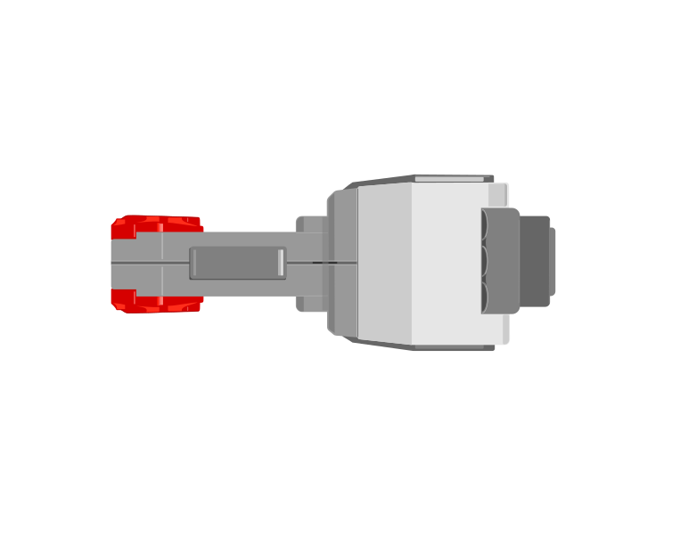
| Block | What it does |
|---|---|
([A v] degrees counted :: sensors) | Reports how far this motor has actually turned since the count was last reset, in degrees. |
[A v] reset degrees counted :: motors | Sets the count back to zero, making right here the new reference point. |
([A v] speed :: sensors) | Reports how fast the motor is turning right now, as a percentage. A motor that is being driven but reads zero is a motor that is stuck. |
Those two are not always the same. Here are two identical motors, running the same program, with only their mechanisms different.
the same program, on two identical motors
Nothing on the Brick announces a stall. The only evidence is that the counter stopped changing while the motor was still being told to turn.
Nothing on the Brick announces the jam. The motor is still being driven, the program is still sitting on the same block, and the only trace of the problem anywhere is a counter that has stopped climbing. Comparing what you asked for with what was counted is how a robot notices — which is the whole of stall detection.
When the Brick powers on, the count is simply whatever it happens to be. It is not a position on the machine — it becomes one only when you tie it to something physical.
That is what reset degrees counted is for, and it is not just a tidy-up block for the top of a program. Where you put it decides what zero means, so putting it part-way through — after the mechanism has been driven somewhere known — is the normal way to use it, not an abuse of it.
A conveyor has no idea where it is. Give it a touch sensor at one end and it can find out: drive it until the sensor is pressed, and it is now at a place you can name. Only then reset the count, and that end becomes 0.
when program starts :: events hat
[A v] start motor [counterclockwise v] :: motors
[1 v] wait until [pressed v] :: sensors
[A v] stop motor :: motors
[A v] reset degrees counted :: motors
The order is the whole point. Reset before the sensor is pressed and you have zeroed a random spot; reset after it, and every later reading means “how far from home”. This is called homing, and it is why a printer rattles its head to one side when you switch it on.
Drive towards home gently. The mechanism is deliberately being run into its own end stop, so a slow speed saves the gears — and the touch sensor is what stops it, which means it stops in the same place every time regardless of where it started.
Home is often a corner, and a corner is an awkward place to measure from. Say the conveyor carries a chute that dispenses bricks, and you would rather describe its position as left and right of the middle. Then home once, drive the known distance to the middle, and reset again there:
when program starts :: events hat
[A v] start motor [counterclockwise v] :: motors
[1 v] wait until [pressed v] :: sensors
[A v] stop motor :: motors
[A v] reset degrees counted :: motors
[A v] run [clockwise v] for (900) [degrees v] :: motors
[A v] reset degrees counted :: motors
Now the middle is 0. Moving right counts up, moving left counts down past zero into negative numbers — the count is perfectly happy to go negative — and “go back to the middle” becomes the simplest instruction in the program: drive until the count reaches 0.
Both resets earn their place. The first one turns a meaningless number into a distance from a real, repeatable place. The second one moves zero to where the maths is easiest. A reset in the middle of a program is only a mistake when the mechanism is somewhere you cannot name.
Because the count is in degrees, and a wheel of known size travels a known distance per turn, the reading can be converted into how far the robot has actually driven. That is how a robot reports a distance in centimetres rather than in rotations — and it is why changing the wheels changes the answer.
This is how a printer knows the paper jammed, how a car window stops when it meets your hand, and how a robot arm knows it has reached its limit. A machine that can only give orders is fragile; one that can check what happened can recover.
Find out how many degrees make one centimetre, once. Then program in centimetres.
Two meshed gears are a bargain. Whatever one of them gains in turns it loses in force, and whatever it loses in turns it gains in force. There is no arrangement of gears that gives you more of both, and no amount of building will find one.
Count the teeth on the gear you are turning (the driver) and the teeth on the one being turned (the follower). That is the whole calculation:
turns out = turns in × driver teeth ÷ follower teeth
An 8-tooth gear driving a 24 gives ⅓ of a turn out for every turn in — and three times the turning force. Turn the pair round and you get three turns out and a third of the force. Count the turns yourself below.
The number of teeth is the whole story. 8 teeth driving 24 means 8 ÷ 24 of a turn out for every turn in — and the force changes by exactly the opposite amount.
| Arrangement | Turns | Force | What it is for |
|---|---|---|---|
| Gearing down — small driving large | fewer | more | winches, lifts, robot arms, anything that has to move a weight |
| Gearing up — large driving small | more | less | fans, spinners, launchers, wheels on a light fast robot |
| 1 : 1 — same size | same | same | moving the drive to a different axle, or fixing a direction |
The names are worth getting right because they are backwards from what people expect: gearing down makes the output slower, not smaller, and it is the setting that makes a weak motor able to lift things.
Put several pairs in a row and the ratios multiply. Two 1:3 reductions in series give 1:9 — which is how a Medium Motor ends up able to raise something it could never shift directly. This is also how a gearbox with a sensible number of parts reaches a ratio that a single pair never could: a 40-tooth gear driven by an 8 is 1:5, and doing it twice is 1:25.
Only the first and last gear affect the ratio. Anything in the middle passes the motion along and changes nothing but the direction — which is a whole idea of its own, in Changing the direction of a turn.
Every mesh loses a little to friction, so a long train is less efficient than a short one. Gearing down far enough to lift a heavy load also makes the mechanism slow, and slow is not always acceptable. And a gear train that is geared down hard is very hard to turn backwards by hand, which is either a useful brake or a nuisance depending on what you are building.
A bicycle is the same idea with a chain instead of teeth in mesh: the low gear that gets you up a hill is turning the back wheel slowly and pushing hard, and the high gear you use going downhill does the opposite. Cars, drills, cranes and clocks are all making the same trade.
Say this back before moving on: “The motor counts degrees. The door is measured in centimetres. Somebody has to convert.”
Look at your model. Count the X pairs in the lattice. That number is part of your machine’s behaviour even though it appears in no program.
| Part | What it is doing here |
|---|---|
| EV3 Intelligent Brick | The fixed door post. One end of the lattice is anchored to it, and it must not slide — everything is measured from here. |
| Medium Motor | Drives the cart along. Its encoder is the only measurement of the door’s position, and it counts in degrees of motor, not of door. |
| Ultrasonic Sensor | Watches the approach. It is looking for a person, so it wants to see along the path people walk, not across the doorway. |
| The scissor lattice (not electronic) | The multiplier. Every X pair you add moves the far end further per turn of the motor — and makes it weaker. |
| The cart and its wheels (not electronic) | Turns rotation into travel. Bigger wheels mean more door per degree, which changes your ratio too. |
Sensors go in ports 1, 2, 3, 4. Motors go in ports A, B, C, D. They are not interchangeable, and nothing will tell you politely if you swap them.
| Part | Port | Why this one |
|---|---|---|
| Cart drive (Medium Motor) | A | One motor doing its own job. |
| Approach sensor (Ultrasonic) | 4 | The Ultrasonic’s standing home. |
Check your own wiring now:
Two routes, and either is fine. USB is the reliable one and the one to fall back on when a room’s Bluetooth is busy; Bluetooth leaves the robot free to move, which some models need.
Do these in order. Naming the Brick after you go looking for it in the list is how groups end up driving each other’s robots.
EV3 until somebody changes it.EV3.The two failures, every class, every time. The Brick has gone to sleep while you were building — press the centre button to wake it. Or you have paired with the group at the next table, which is why the name matters.
The long version, including Port View and how to read the port tiles, is in the Brick & Bluetooth guide.
The Brick is a structural part of this model. It anchors one end of the lattice, so anything tugging on it moves the door’s zero point. Route a USB cable so it cannot pull the Brick sideways, or use Bluetooth.
Stuck? The long version, with a photograph of every screen, is in the Brick & Bluetooth guide.
One change at a time. Keep a ruler beside the door — most of today’s answers are in centimetres.
Step 3 is the one to remember. Nothing in the program was wrong, and the machine behaved differently, because a number the program depends on was never in the program. It was in the plastic. Write your ratio on a card and keep it with the model.
A program full of tuned numbers is a program that only works on the machine it was tuned on.
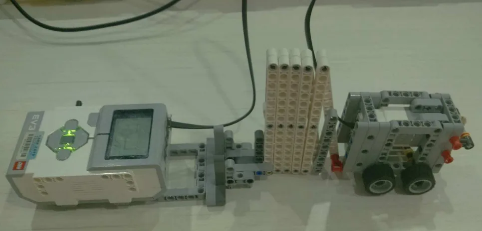
Build the model before you read any further. Everything after this is about making it do something, and none of it will make much sense with nothing on the table in front of you.
Use the viewer's own controls to zoom and turn pages. Fullscreen makes it big enough to build from.
Check the finished build against the picture before you switch anything on. A motor mounted the wrong way round is far easier to spot now than it is to debug later, when it looks like a program fault.
Open when somebody comes, hold while they pass, close when they are clear.
when program starts :: events hat
[A v] reset degrees counted :: motors
clear display :: display
write [PINTU SEDIA] at line (1) :: display
forever
  [4 v] wait until distance [< v] (30) [cm v] :: sensors
  write [BUKA    ] at line (1) :: display
  [A v] run [clockwise v] for (700) [degrees v] at (40) % speed :: motors
  wait until <([4 v] distance in [cm v] :: sensors) > (50)>
  wait (2) seconds
  write [TUTUP   ] at line (1) :: display
  [A v] run [counterclockwise v] for (700) [degrees v] at (40) % speed :: motors
end
What success looks like: walk a hand towards the door. It folds open, waits while your hand passes, waits two seconds more, and folds shut — back to exactly where it started, not a little further open each time.
If the door creeps further open each cycle, it is stalling against a stop on the way out and losing that movement on the way back. Reduce your degrees a little — the safe travel is slightly less than the full travel.
Work through them in order — each is harder than the last. The extra challenge comes after all three, and it is meant to make you plan before you build.
Open the door to exactly 5 cm, then exactly 10 cm, using your measured ratio. Check both with a ruler.
Make the door open only as far as it needs to: a small opening for a hand, the full opening for a whole box.
Add or remove one X pair from the lattice, re-measure your ratio, and get the door back to exactly 10 cm.
Build a two-speed door: quickly to 80% open, then slowly for the last stretch, and slowly all the way when closing. It must return to exactly closed on every cycle — prove it by running twenty cycles and measuring the closed position afterwards.